Topics
- Simulation of next-gen automotive perception
- Cooperative fusion for tracking of pedestrians from a moving vehicle
- Radar pedestrian detection using deep learning
- Multimodal vision
- Automotive High Dynamic Range (HDR) imaging
- Efficient multi-sensor data annotation tool
- Point-cloud processing
- Environment mapping and odometry
- Real-time sensor data processing for autonomous vehicles using Quasar - demo video
Simulation of next-gen automotive perception
Current automotive perception systems fall short of level 5 anywhere–anytime autonomous driving capability. Novel sensor technology will be needed to address the bottlenecks in robustness to low-light situations, adverse weather and unforeseen traffic interactions. However, experimental sensor tech has to overcome several barriers:
- Need to build prototype sensors for field testing
- Need to integrate them into existing perception systems
- Need to capture, label and process huge amounts of data
- Need to overcome risk-averse investment attitudes of cost-driven industry.

Sensai virtual sensor modelling
In the SENSAI project, we build generative AI powered virtual sensor models to be able to simulate corner case scenarios for autonomous driving and assess the value of next-generation sensing as addition to a reference sensor fusion stack to resolve these corner cases. GenAI model prediction of Short-Wave InfraRed (SWIR) applied to real data, compared to actual recorded SWIR.
We combine physics layers with learnable pixel-wise reflectivity prediction layers to simulate infrared imaging, frequency modulated continuous wave (FMCW) lidar and radar in our CARLA-based virtual world, allowing us to perform multi-modal object detection in parametric scenarios and to explore the specifications and requirements for future sensor suites.
Simulation of SWIR in a dusk scenario, using CARLA and Unreal Engine 5 and our custom asset library.
Virtual lidar model simulating realistic 850 nm ToF lidar returns, as presented at 2024 IEEE Sensors conference.
FMCW radar simulation with learning-based EM reflectivity model and parametric radar antenna array.
Fused RGB–SWIR–lidar pedestrian detection in context-adaptive sensor fusion framework.
Please contact one of the authors below to obtain login credentials for the download.
References
[1] Dimitrievski, Martin, et al. “Physically Accurate Lidar Simulation for Automotive Digital Twins.”, IEEE Sensors 2024, 23rd IEEE Conference on Sensors, Proceedings, IEEE, 2024.
Contact: dr.ir. David Van Hamme, dr.ir. Martin Dimitrievski
Cooperative fusion for tracking of pedestrians from a moving vehicle
Autonomous vehicles need to be able to detect other road users and roadside hazards at all times and in all conditions. No single sensor is dependable enough for this task, hence sensor fusion is required.
Current multi-sensor perception systems on the market rely largely on late sensor fusion, in which the outputs of the sensors are combined only at the object level. This means that that each sensor acts completely independently and all low level information that did not exceed a detection threshold is completely discarded. This loss of information is problematic as a hard-to-see object may be missed by one or more of the sensors, and cannot be recovered by the fusion algorithm An obvious solution would be to combine the sensor data at the lowest level possible, an approach which can be found in academic literature and does indeed provide superior object detection. However, this solution is not feasible for a car manufacturer to implement for several reasons. Firstly the bandwidth requirement for a modern vehicle with multiple cameras, multiple radars, proximity sensors and possible lidar is simply too big. Secondly, jointly processing this heterogeneous data is difficult to optimize on power efficient hardware, an important drawback especially for an all-electric future. Thirdly, low level sensor fusion requires extensive cross-domain knowledge which is fragmented across different subsystem suppliers.
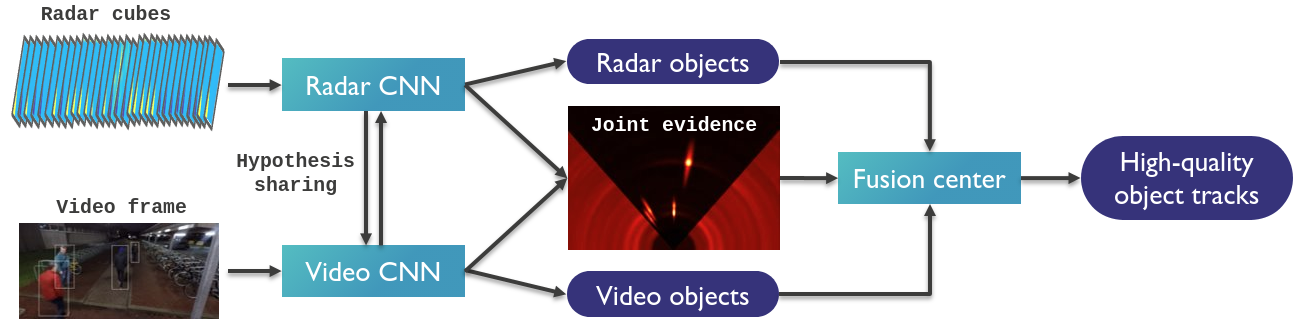 System diagram for cooperative fusion.
For these reasons, we propose the concept of cooperative sensor fusion. This builds on late fusion with two important changes. Firstly, sensors not only share objects, but also intermediate level evidence maps. These evidence maps require much less bandwidth to the fusion center than raw data would, yet they retain the sub-threshold information the fusion algorithm needs to resolve ambiguities and made good decisions on hard-to-see objects. This results in 22% lower localization error for nearby pedestrians compared to late fusion. Secondly, the sensors are able to influence each other's processing by sharing candidate objects (= object hypotheses) with each other. In this way a sub-threshold signal may be boosted and produce an object based on the suggestion of another modality, making the job of the fusion center much easier. The result is a 23% reduction in pedestrian miss rate in difficult circumstances, compared to the same implementation without hypothesis sharing between sensors.
Additional information:
Keep reading to find out more about our cooperative fusion research:
Radar-Video sensor fusion
The following video demonstrates the improved accuracy of radar-video fusion:
Video: Top: Detection of vulnerable road users relying solely on radar information. Bottom: radar and RGB fusion based detection.
Contact: dr.ir. David Van Hamme, MSc Martin Dimitrievski
LIDAR-Radar-Video sensor fusion
Our camera-lidar-radar cooperative fusion method is capable of detecting and tracking road users under nominal as well as in border cases of system operation. The fusion algorithm is based on a sensor-agnostic Bayesian framework, augmented with an optional exchange of detector activation information between sensors, referred to as cooperative feedback. The system was deployed on two sensor setups: the NuScenes test vehicle with of 6 cameras, 1 LIDAR and 5 RADARs, and our own prototype vehicle with 1 camera, LIDAR and RADAR. We process camera images using the state-of-the-art FCOS-3D object detector, the LIDAR point clouds using the Centerpoint object detector, and the radar data cubes using a Radar CNN detector developed by our team. Results obtained from extensive experimental evaluation confirm that we obtain competitive detection and tracking performance in normal operation. The main benefit of the proposed method is in cases of sensor failure where, due to the probabilistic modeling, we observed significant improvements in both detection and tracking accuracy over state-of-the-art trackers such as CenterTrack and CBMOT.
The following video illustrates the output of our tracker, tested on a few of the test sequences captured by our own prototype platform.
References:
Martin Dimitrievski, David Van Hamme, and Wilfried Philips, "Perception System Based on Cooperative Fusion of Lidar and Cameras", in IEEE SENSORS conference 2022 (accepted)
Martin Dimitrievski, David Van Hamme, Peter Veelaert and Wilfried Philips, "Cooperative Multi-Sensor Tracking of Vulnerable Road Users in the Presence of Missing Detection", MDPI Sensors 2020, 20(17), 4817;
Contact: dr.ir. David Van Hamme, MSc Martin Dimitrievski
Radar pedestrian detection using deep learning
Radar can be a powerful component of a multi-sensor perception system for autonomous vehicles, AGVs or in other mixed human-robot environments. However, traditional radar processing techniques fail to leverage the power of FMCW radar to detect pedestrians using their micro-Doppler signature. At IPI we have developed a CNN that processes stacked consecutive range-azimuth-Doppler cubes. Tests both on outdoor, moving-platform data and indoor fixed-sensor scenarios demonstrate that the CNN is able to better distinguish people from background clutter and better determine their exact position compared to 3D CFAR methods operating on single radar cubes.
Video: Top: Detection of vulnerable road users relying radar CFAR processing. Bottom: CNN based radar pedestrian detection.
An excerpt of the dataset used for this research can be downloaded here. Please contact one of the authors below to obtain login credentials for the download.
References:
- M. Dimitrievski, I. Shopovska, D. Van Hamme, P. Veelaert, and W. Philips, "Weakly supervised deep learning method for vulnerable road user detection in FMCW radar," in 23rd IEEE International Conference on Intelligent Transportation Systems (ITSC 2020), Proceedings, Rhodes, Greece, 2020.
Contact: Dr.ing. David Van Hamme, MSc Martin Dimitrievski
Multimodal vision
Reliable visibility of traffic participants in all weather conditions is crucial for driving safety. An advanced driver assistance system (ADAS) should provide the driver with an augmented representation of the vehicle surroundings, including imagery which improves the visibility in adverse atmospheric conditions. For autonomous driving, the vision system of an autonomous vehicle needs to create a complete representation of the environment, including all traffic participants, the current traffic conditions, and the road signalization.
Keep reading to find out more about our multimodal vision research:
- 2D multi-modal video fusion for wide-angle environment perception
- Visible-thermal video enhancement for detection of road users
2D multi-modal video fusion for wide-angle environment perception
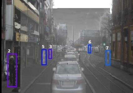
In our research we have focused on a camera-based multi-sensor setup with overlapping and non-overlapping views. Our sensor subset consists of the following passive cameras/sensors: Front, visible light RGB camera (FVL), Front, long-wavelength infrared camera (LWIR/thermal), Left (LVL) and right (RVL) side, visible light cameras. The visible- and thermal cameras are complementary for different visibility and weather conditions. The proposed object-tracking and fusion method performs individual detection and temporal smoothing (tracking) in each camera, and fusion at the decision level in a joint viewt, which significantly improves the accuracy of the detected pedestrians. The result is shown the figure below, where images from different cameras are shown overlapped.
Video: The result of pedestrian tracking and fusion across cameras with disjoint views, and cameras capturing different electromagnetic bands with overlapping views
References:
- Ivana Shopovska, Ljubomir Jovanov, Peter Veelaert, Wilfried Philips, Merwan Birem and Kris Lehaen, "A Hybrid Fusion Based Frontal-Lateral Collaborative Pedestrian Detection and Tracking", IEEE 20th International Conference on Intelligent Transportation Systems Yokohama, JAPAN, October 16 - 19, 2017
Contact: dr.ir. Ljubomir Jovanov, MSc Ivana Shopovska
Visible-thermal video enhancement for detection of road users
In highly changing and in adverse visibility conditions, the color and thermal cameras are complementary sensors that can be combined in a joint vision system where one sensor compensates for the limitations of the other.
Our task-specific color and thermal fusion method is designed to enhance the visibility of vulnerable road users in urban traffic scenes. The fusion algorithm is a deep learning-based method that was trained enhance the appearance of pedestrians using the feedback of an object detector connected in a joint pipeline. It relies on the robustness of the thermal camera to the amount of ambient light, to perceive the presence of vulnerable road users (VRUs).
The two videos below show the output of our method in challenging light conditions, where vulnerable road users (VRUs) disguised in the dark areas are enhanced in the output. By combining the two complementary sensors, a human driver or a detection algorithm can perceive the surrounding scene, as well as recognize the presence of pedestrians or cyclists, where relying on regular color vision would be impossible.
References:
- I. Shopovska, L. Jovanov and W. Philips, "Deep Visible and Thermal Image Fusion for Enhanced Pedestrian Visibility", Sensors, vol. 19, no. 17, pp. 1–21, 2019.
Contact: dr.ir. Ljubomir Jovanov, MSc Ivana Shopovska
Low-latency crossing-pedestrian detection with RGB + event cameras
Stopping safely often comes down to seeing a person the moment they step into the road. We fuse detection results from RGB cameras with event cameras, which react to brightness changes at microsecond resolution and is highly sensitive to motion. A lightweight geometry step removes ego-motion from the event stream, and a simple likelihood test then combines the RGB detector’s confidence score with an “active pixel percentage” score from the events. This cleanly distinguishes moving pedestrians from static background and reduces decision latency. In CARLA simulations the fusion detects pedestrians about 216 ms earlier (≈ 1.0–1.1 m extra reaction distance at urban speeds) and substantially improves accuracy compared to RGB-only detection (F1 +113%, precision +69%, recall +68%). The method is interpretable and real-time, so it is practical for safety-critical perception.
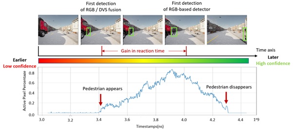
RGB-DVS fusion
References:
- B. Huang, G. Allebosch, P. Veelaert, T. Willems, W. Philips, and J. Aelterman, “Low latency pedestrian detection based on dynamic vision sensor and RGB camera fusion,” in Proceedings of the 20th International Joint Conference on Computer Vision, Imaging and Computer Graphics Theory and Applications. VISAPP, Porto, Portugal, 2025, vol. 2, pp. 841–850.
Contact: prof.dr.ir. Jan Aelterman
Online Sensor Selection for Object detection
Object detection using multiple sensors can be challenging when coupled to constraints on computation, energy, and data transmission. Processing data from all sensors in every situation may be infeasible due to such constraints, making it difficult to efficiently leverage the strengths of each sensor.
We propose a method for online sensor selection, which dynamically decides, based on the current situation, which sensors' data to process (and which sensors to ignore/disable). These decisions help to satisfy constraints, but are made intentionally to still maximize the overall detection performance.
This approach is particularly useful for self-driving cars, surveillance, industrial automation, and smart health, where fast and efficient object detection is essential. As shown in the video, we demonstrate our method with a case study for detecting vehicles while switching between high- and low-resolution sensors in an effort to reduce the number of pixels processed (=compute cost). The results show how this proposed approach outperforms the medium-resolution baseline in both detection performance and compute cost, measured as the number of pixels processed.
Video: This video shows car detections and the number of pixels processed on the KITTI dataset. It compares our online sensor-selection method, which switches between low- and high-resolution sensors, against a baseline that always uses a medium-resolution sensor. As shown, our method detects more cars, keeps false detections very low, at a lower compute cost."
Contact: dr.ir. David van Hamme
Automotive High Dynamic Range (HDR) imaging
The range of light intensity that reflects from the scene and falls onto the sensor is often called a dynamic range of the scene. Real world scenes have a very high dynamic range that cannot be captured by standard cameras. Furthermore, the light conditions in video sequences of traffic environments captured from moving vehicles can be highly variable. As the vehicle moves, different shadows, direct sunlight, headlights of the approaching cars etc. are creating extreme contrast in the image, which causes performance drop in computer vision algorithms employed for autonomous driving or driver assistance.
High dynamic range (HDR) imaging helps to capture more details of scenes with extreme contrast and with that to improve the quality of details in the captured video stream. In our research of HDR imaging we have focused on the reconstruction of HDR data by combining multiple exposures, as well as on intelligently tone mapping the HDR data to enhance the performance of object detectors while preserving perceptual quality for visualization.
Keep reading to find out more about our HDR research:
- Classic multi-exposure HDR reconstruction
- Intelligent HDR tone mapping for traffic applications
- Learning-based HDR video reconstruction and tone mapping
Classic multi-exposure HDR reconstruction
To increase the captured dynamic range of the scene, along with the automatic optimal exposure time (base exposure), we capture one longer and one shorter exposure frame to capture objects hidden in the shadows and in brightly illuminated regions. A selective weighted averaging-based method is employed to combine the well-exposed details in each input into a HDR representation.
In automotive HDR fusion, one of the main challenges is dealing with motion in the scene. Since multiple frames are captured in consecutive time moments, motion in the scene can cause significant motion artifacts. To reduce the artifacts caused by global camera motion we employ non-rigid motion estimation. Local motion artifacts are reduced by a deghosting technique that recognizes significant differences in intensity between motion-compensated inputs and selects only one input to fill-in the ghosting-prone regions. The resulting images are much more informative than the images captured using base exposure time.
References:
- Shopovska, I., Jovanov, L., Goossens, B., & Philips, W. (2016). "HDR video synthesis for vision systems in dynamic scenes," Proceedings of SPIE (Vol. 9971, p. 99710C–99710C–16). Conference on Applications of Digital Image Processing XXXIX , SPIE.
Contact: dr.ir. Ljubomir Jovanov, MSc Ivana Shopovska
Intelligent HDR tone mapping for traffic applications
To capture and faithfully represent HDR scenes, special camera sensors and ISPs have been proposed, with improved sensitivity and saturation compared standard dynamic range (SDR) cameras. Such HDR content is stored in representations of up to 24 bits, to limit the loss of information.
However, HDR data of high bit-depth can be incompatible for visualization in ADAS as most displays use 8-bit representation. Moreover, most computer vision algorithms are trained to work with 8-bit SDR images. Therefore, a non-linear transformation of the pixel intensity range called tone mapping is often employed to convert the HDR data into a lower bit-depth representation, with the goal to preserve details in both the shadows and bright areas of the image without noticeable artifacts.
In our research we trained a convolutional neural network that intelligently tone maps HDR video frames into SDR representation, with the goal to preserve the details relevant for accurate object detection. Training the model relies on feedback from object detection performance. We also apply various data augmentation steps that resemble typical variations that can be encountered in driving situations to improve the robustness.
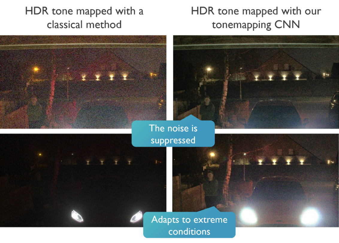 Comparison of the proposed learning-based method to state-of-the-art in classical tone mapping
Contact: MSc Ivana Shopovska, MSc Ana Stojkovic, dr.ir. Jan Aelterman
Learning-based HDR video reconstruction and tone mapping
Our multi-exposure high dynamic range (HDR) fusion method uses a lightweight neural network model trained to select and combine the well-exposed details in two input frames: an over-exposed frame (optimal for shadows) and an under-exposed frame (optimal for bright regions), into a single overall well-exposed frame. Compared to the majority of the state-of-the-art HDR methods, our algorithm is optimized for application in object detection, instead of artistic quality.
The proposed solution can be used in combination with regular color cameras, compared to more specialized HDR sensors and ISPs. Since our method performs both HDR fusion and tone mapping, it results in lower bit-depth output, reducing computations in the rest of the pipeline. The video highlights the benefits of using the proposed solution in low-light, high contrast urban traffic scenes which are some of the most challenging light conditions for regular cameras as well as for human drivers.
Contact: MSc Ivana Shopovska, dr.ir. Jan Aelterman
Efficient multi-sensor data annotation tool
To train deep learning models, large datasets are typically required for modeling accuracy and robustness. To facilitate the research and enable fast data annotation, we have been exploring efficient ways to annotate our own multi-sensor datasets, as an alternative to labor-intensive manual labeling.
Our current tool visualizes the data from all sensors into a common field of view and enables easy supervision and correction of an automatically proposed labeling solution, as a tradeoff compared to precise but slow manual annotation.
Video: demonstration of the IPI multi-sensor data annotation tool. NOTE: the video includes audio narration.
Reference:
- M. Dimitrievski, I. Shopovska, D. Van Hamme, P. Veelaert, W. Philips, "Automatic labeling of vulnerable road users in multi-sensor data", in ITSC2021 24th IEEE International Conference on Intelligent Transportation, IEEE ITSS Intelligent Transportation Systems Society, 2021.
Contact: MSc Martin Dimitrievski, MSc Ivana Shopovska, dr.ir. David Van Hamme, dr.ir. Jan Aelterman
Low-level point-cloud processing
Normal estimation
Recognition of objects in point cloud data relies on cues of the local 3D geometry and most of the algorithms use local plane normal information in one form or the other. Therefore, fast computation of local plane normals is of paramount importance. Part of our research resulted in the development of an algorithm for fast computation of plane normals in single Lidar configuration. Our approach transforms the point cloud to a spherical depth image where it exploits fast image processing paradigms. Within this depth image we employ a robust, block processing based, plane fitting algorithm to estimate the local normals. This approach completely skips the expensive nearest neighbor search operation and enables our local plane estimator to run real-time even in dense point clouds. The algorithm development, from design to implementation, was completely done using the Quasar programming language.
Video: Color coded point cloud with the orientation of the local plane normals relative to the vehicle
Up-sampling
Our contribution is an efficient and semantically accurate algorithm for generation of dense depth maps using sparse LIDAR point cloud data. Using a reformulation of the bi-lateral filter we fill-in missing measurements, preserve the object edges and suppress the measurement noise. Our dense depth maps can be used in various computer vision systems as data modality or they can be back-projected to obtain a more dense point cloud. Experimental results on KITTI, sequence 19 and 16:
Video: Top: RGB camera frame, Bottom: reconstructed dense depth map
Video: Top: RGB camera frame, Bottom: reconstructed dense depth map
Contact: ir. Martin Dimitrievski
Point-cloud based Object detection and tracking
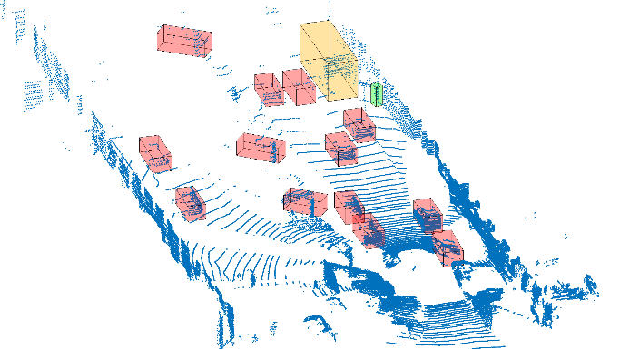
Point Cloud based object detection is performed by first removing points that lie at or near the local ground plane. The remaining points are segmented into semantically meaningful objects by using projective geometry. A height map is processed using various image morphology techniques to extract local variances defining object boundaries. Finally, the processed height map contains connected components, i.e. blobs, which coincide with the contours of the 3D objects. Points in the original point cloud are therefore segmented to the respective object contour.
Tracking of objects is performed in the connected components (blobs) image on a frame-by frame basis. This blob image is first corrected for EGO motion using our LiDAR odometry algorithm and then matching blobs are tracked over time using maximum overlap criterion.
The following video demonstrates the results of our odometry, detection and tracking:
Video: Top: Segmentation of the LiDAR point cloud with ground plane colored gray, bottom: corresponding segments projected on the RGB image. (click here for full-screen video)
Using the ground truth data in the KITTI dataset we trained a purely point cloud based car classifier. The model was built on a combination of Fast Point Feature Histograms (FPFH) and statistical moments from 3D points and a non-linear SVM classifer. A multiple target Kalman filter tracking technique is later used on the cars to accurately track and predict their speeds and velocities.
|
|
Contact: ir. Martin Dimitrievski
Liborg - Lidar based mapping
Today, the 3D reconstruction of, for example, tunnels or industrial buildings is a time-consuming and expensive process. To simplify this process we developed Liborg, a lidar-based mobile mapping platform. The system is independent from any external positioning system such as GPS and conducts localization (inherent to mapping) solely based on the output of a lidar scanner. Thanks to our efficient 3D mapping algorithms, it is possible to build detailed 3D models of various environments on the fly. Furthermore, we developed a system to transmit the reconstructed 3D model to a remote computer or server. This latter allows a whole range of additional applications for which Liborg can be used such as live monitoring of the acquired 3D model, for instance to perform inspection or assess damages in areas that are difficult to reach.
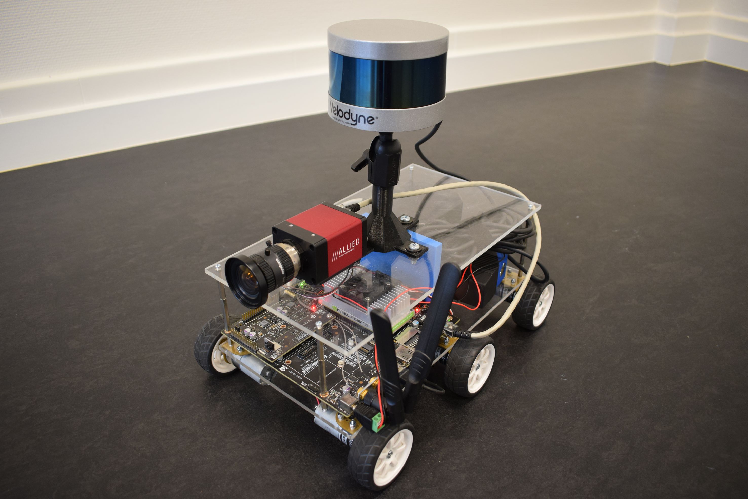
Recently, we started the development of a truly autonomous robot, in a way that it will be possible for the robot to perform navigation based on its own acquired 3D model. This allows the robot to perform the entire 3D mapping of a scene without any manual intervention. We also integrated a regular camera to be able to combine the 3D geometric information of the scene with visual data. To that end, a synchronisation module was developed along with calibration algorithms to relate the data of both sensors. A picture of our autonomous robot can be found below. Note that it is still possible to control it remotely or to use our 3D mapping software in combination with another kind of sensor set-up, including a hand-held lidar scanner.
The main technological benefits of Liborg are: 1) fast, accurate and highly robust point cloud registration (stitching), 2) unrivalled sub centimeter accuracy and 3) a compact and efficient representation of the 3D model. The overall advantages of Liborg summarize as follows. First, it is no longer necessary to bring in an external company with specialized equipement. Second, there are no scanners that need to be put into place manually. Third, one can monitor, at all times, which areas have already been assessed or mapped. All this saves both time and money. Below, we demonstrate a few use cases.
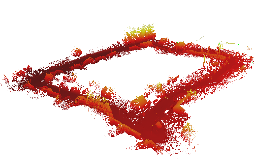
Street mapping in Hasselt
The goal of this use case was to generate a highly precise 3D model of residential are in the vicinity of Hasselt. To that end, we mounted a Velodyne HDL-32E lidar scanner on the mapping van of the company Grontmij. In order to acquire the facades and rooftops of the houses in detail, the scanner was tilted, making an angle of approximately 44 degrees with the ground plane.
|
|
|
UFO building Ghent University
A set of sequences was captured at a campus of Ghent University, near the UFO and Technicum building. Below you can find an example sequence and life 3D reconstruction demo.
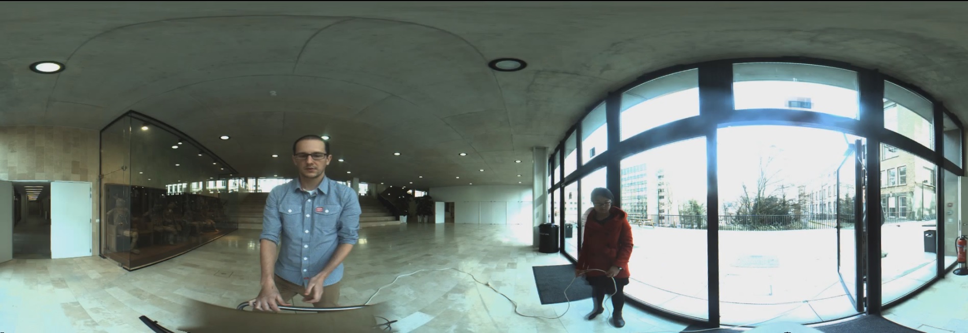 (click on the image to play a video)
|
 (click on the image to play a video)
|
DOW Chemical plant
A third, challenging, use case was recorded at a chemical site of the Dow Company in Terneuzen. This environment was part of a disused area that was planned to be demolished. It consists of a lot of pipelines that were formerly used to carry liquids or gases, as can be seen in the video below. Although this environment seems outdoors, the GPS signal is far too unreliable due to the abundance of pipelines. Below you can again find an example sequence and life 3D reconstruction demo.
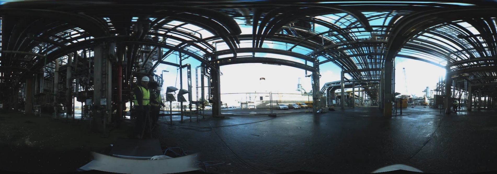 (click on the image to play a video)
 (click on the image to play a video)
References:
- M. Vlaminck, H. Luong, W. Goeman, W. Philips, "3D scene reconstruction using omnidirectional vision and LiDAR: a hybrid approach.", SENSORS, MDPI, 16(11), 2016
- M. Vlaminck, H. Luong, W. Philips, "Liborg: a lidar-based robot for efficient 3D mapping", Applications of Digitial Image Processing XL Vol. 10396, SPIE, 2017
- M. Vlaminck, H. Luong, W. Philips, "Have I Seen This Place Before? A Fast and Robust Loop Detection and Correction Method for 3D Lidar SLAM", SENSORS, MDPI, 19(1), 2019
Contact: ir. Michiel Vlaminck
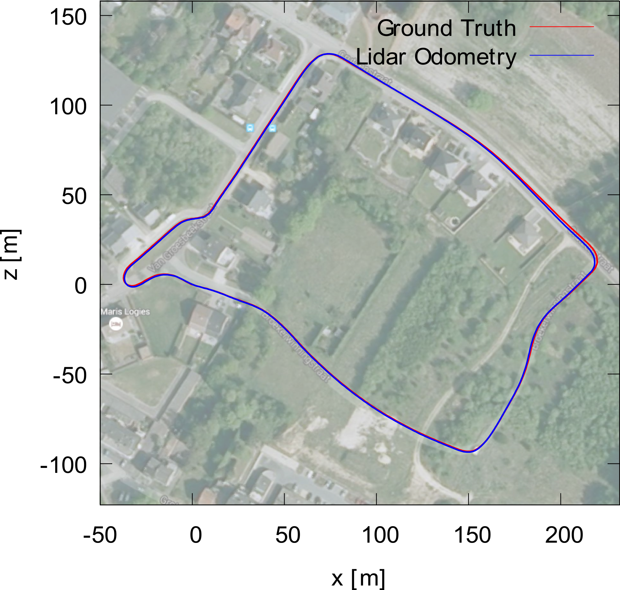
LIDAR based odometry
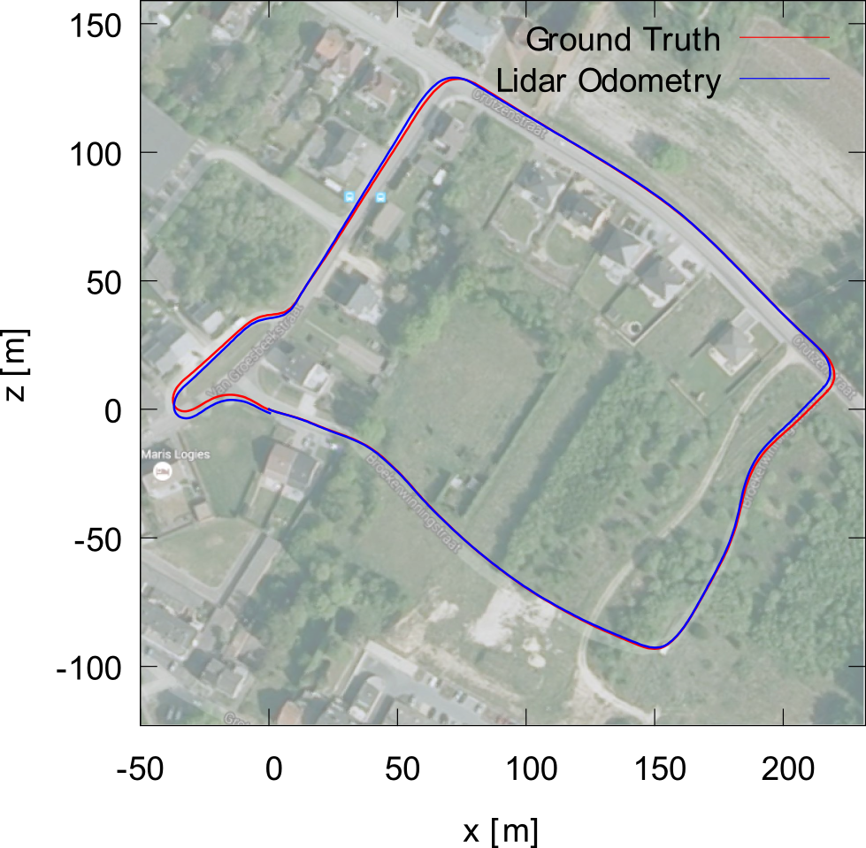
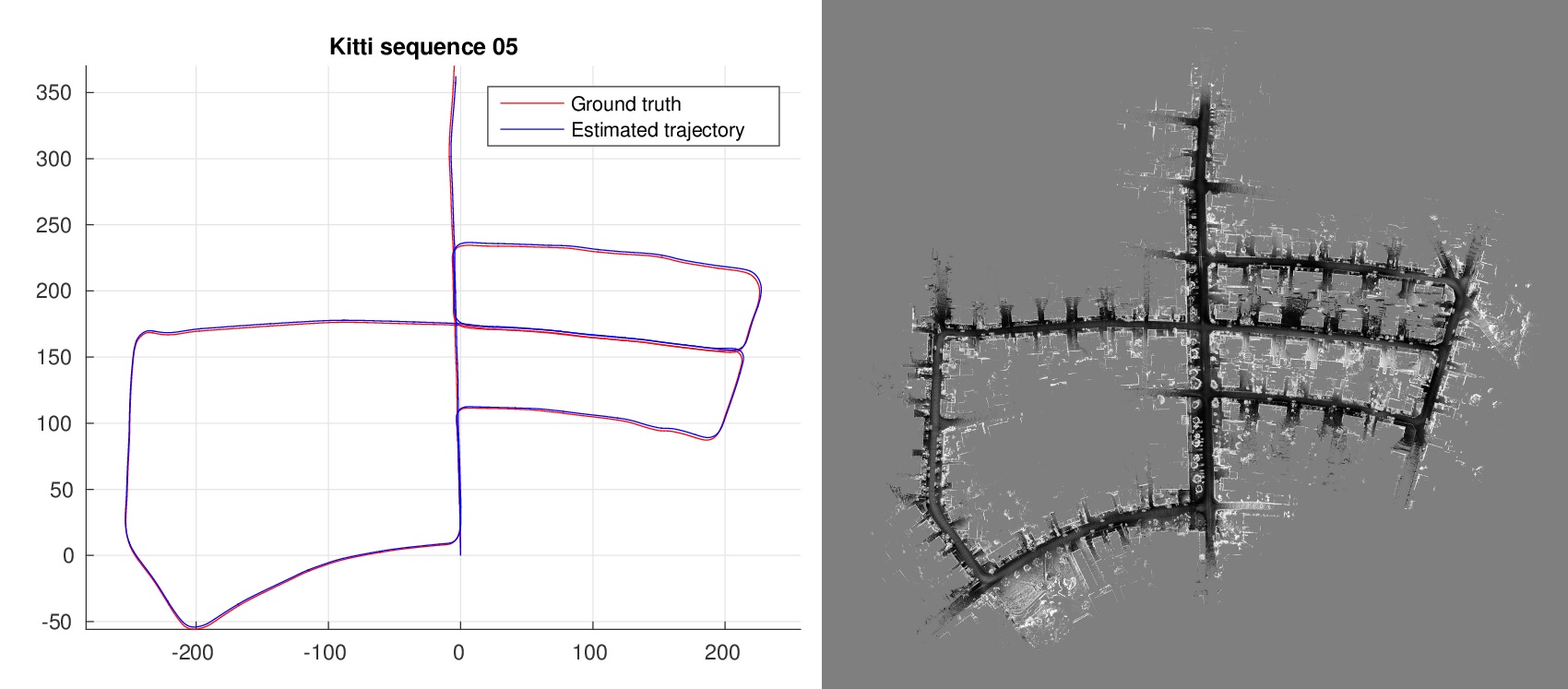
Facing real world driving conditions, autonomous vehicle systems often fail to accurately find their position in space. Computer vision pose estimation techniques rely on camera technology which is highly unreliable in low light levels and/or bad weather. By using point cloud data scanned by on-board Lidar sensors we have developed an ego-localization system for accurate short term odometry. We use projective geometry to reduce the point cloud to a 2D map and then apply robust image registration techniques to estimate the ego-motion. The sensor nature guarantees that our system is invariant to the ambient light levels and atmospheric conditions. Experiments on real-world driving data show improvements in short term localization accuracy over standard Visual Odometry approaches even in perfect light conditions.
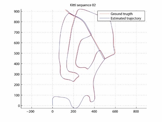
Estimated trajectory
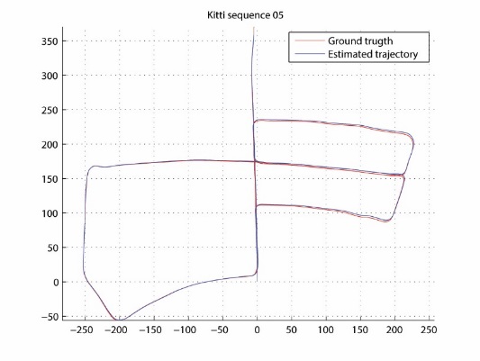
Ground truth (KITTI dataset)
References:
- Martin Dimitrievski, David Van Hamme, Peter Veelaert and Wilfried Philips, "Robust matching of occupancy maps for odometry in autonomous vehicles", in Proceedings of the 11th Joint Conference on Computer Vision, Imaging and Computer Graphics Theory and Applications, pp.626-633, 2016
Contact: ir. Martin Dimitrievski
Monocular visual odometry
Current consumer vehicle navigation relies on Global Navigation Satellite Systems (GNSS) such as GPS, GLONASS and Galileo. However, as new cars are increasingly being equipped with cameras as standard equipment for a variety of tasks (e.g. lane departure warning, collision avoidance, traffic sign recognition), this opens up possibilities for navigation based on visual clues. Our visual odometry method robustly estimates the vehicle's trajectory using a simple monocular camera. The method is easy to calibrate, can accommodate a wide variety of camera mounting positions and yields competitive results with traditional pose estimation methods.
Video: Our visual odometry method applied on a sequence from a Kitty database Our visual odometry method applied on a sequence from a Kitty database (click on the image to play a video sequence) Furthermore, we have proposed a novel algorithm to relate the estimated trajectory to an offline map, effectively eliminating the error accumulation (drift) problem and thereby providing a complete fair-weather vehicle-contained navigation solution, requiring no external communication whatsoever. The high detail in which the trajectory also allows the detection of smaller maneuvers (e.g. lane changes), which is important in the context of intelligent vehicles / ADAS (advanced driver assistance systems).Video: Mapped monocular visual odometry
The method also has possible applications in indoor navigation and cyclist odometry.
References:
Van Hamme, D., Veelaert, P. & Philips, W. (2012). Communicationless navigation through robust visual odometry. In: 15th International IEEE conference on Intelligent Transportation Systems (ITSC 2012), Anchorage, AK, USA, 2012-09-16. IEEE. 1555-1560.
Van Hamme, D., Veelaert, P. & Philips, W. (2011). Robust monocular visual odometry by uncertainty voting. In: 2011 IEEE Intelligent Vehicles Symposium (IV 2011], Baden-Baden, Germany, 2011-06-05. IEEE. 643-647.
Van Hamme, D., Veelaert, P. & Philips, W. (2011). Robust visual odometry using uncertainty models. In: 13th International Conference on Advanced Concepts for Intelligent Vision Systems (ACIVS)/ACM/IEEE International Conference on Distributed Smart Cameras, Ghent, Belgium, 2011-08-22.
Van Hamme, D., Goeman, W., Veelaert, P., & Philips, W. (2015). Robust monocular visual odometry for road vehicles using uncertain perspective projection. In: EURASIP Journal on Image and Video Processing, 1–18.
Contact:dr. ing. David Van Hamme
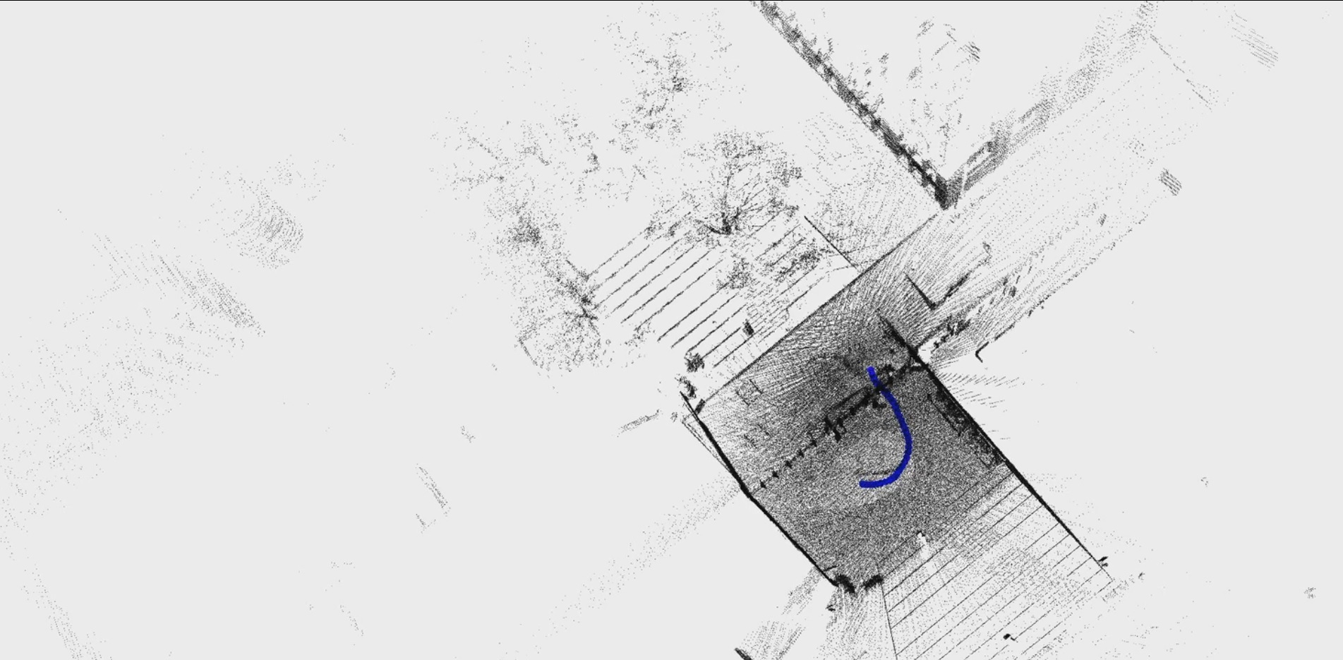
Automotive occupancy mapping
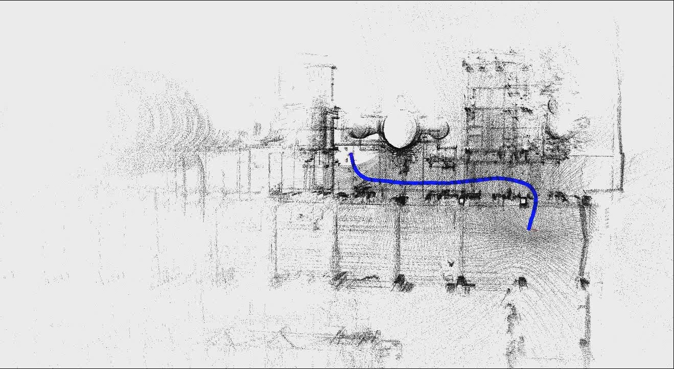
Our autonomous vehicle system perceives a snapshot of the local surroundings by applying the occupancy map model to the point cloud data. Occupancy maps are an elegant solution to the problem of data fusion especially when there is a multitude of heterogeneous sensors on board. Point cloud height information is projected on the local ground plane and a probabilistic model computes the probability of occupancy for each point around the vehicle. Using our previously demonstrated odometry sub-system we can incrementally build this occupancy map resulting in a very detailed picture of the local surroundings.
 Video: Example trajectory and the corresponding environment geometry (click on the image to play a video)
Contact: ir. Martin Dimitrievski
Obstacle detection based on 3D imaging
This research has lead to an obstacle detection system that can assist visually impaired people. The system relies on the output of a 3D sensor (e.g. Kinect) and uses 3D imaging and computer vision to detect obstacles. The obstacle detection process itself involves two main tasks. The first task deals with the reconstruction of the scene in front of the pedestrian while the second task performs a segmentation of the scene based on this reconstruction.
Reconstruction
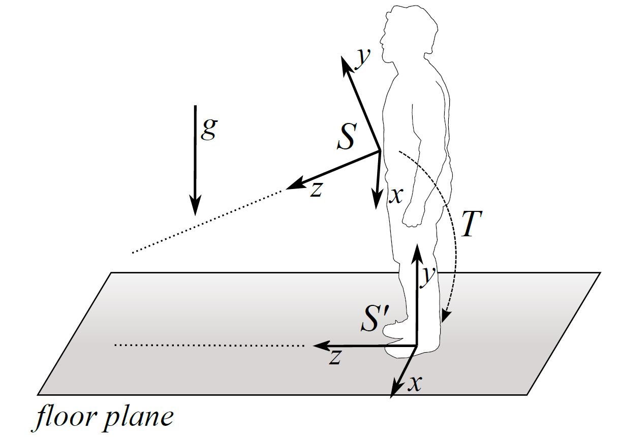
During the reconstruction phase, depth and color information are combined to create a colored point cloud. Once the point cloud is created, we transform it in order to allign the floor plane with the xz-plane in our reference system. This transformation can be carried out because the Kinect is equipped with an accelerometer which provides us with the direction of the gravity. The importance of the transformation is threefold. First, it is needed to keep the consecutive point clouds expressed with respect to the same reference system. Secondly, the detection of the floor plane is simplified and more robust since we do not have to assume that the floor plane is the dominant plane in the scene. Finally, this transformation will enable us to make use of the absolute position of objects in the scene, in particular of the absolute height of the obstacles. The figure below illustrates the idea of the performed reconstruction and transformation.
Illustration of the coordinate system transformation. During the transformation, the xz-plane is alligned with the floor plane and the origin is centered at the feet of the pedestrian. The performed transformation.
 |
Segmentation
The segmentation process consists of two subtasks. The first task will segment all the dominant planes in the scene. Obviously, the most important plane in the scene is the floor plane since most obstacles are lying on it. Once we have identified the floor plane, we can classify objects as obstacles from the moment they are located right in front of the pedestrian. The second task thus consists of the segmentation of the remaining objects. The easiest way to do this is to cluster the remaining points based on their distance relative to each other. Below you can find a video showing how the system is performing. The scene was recorded at one of the corridors of our research group making use of a Kinect sensor.
Video: Our obstacle detection method
Step detection
In some cases obstacles do not have to be avoided. When the obstacle takes the form of a staircase, the pedestrian can simply go upstairs. For this reason, this work also covers the detection of steps. This latter process is based on a piecewise planar model. After the different planes of the scene are segmented, we check if there are any planes parallel with the floor plane that are located at a certain height. The detection of steps in the scene is solely based on depth information. As a result, the algorithm can operate in situations subject to different light conditions. Below you can find an example segmentation of the different steps in the scene.
Door detection
The same reasoning applies in cases where the obstacle is a door. Instead of avoiding this obstacle, the door can be opened. The detection of doors also appeals on the plane segmentation process. This time we check if there is a plane that is perpendicular to the floor plane and has a certain width. Once such a plane is found, we check if a door handle is present at a certain position. The plane segmentation process is extended to take color information into account since a door is often part of the same plane as the wall. Below you can find an example segmentation of a door.
References:
- Vlaminck, M.; Jovanov, L.; Van Hese, P.; Goossens, B.; Philips, W.; Pizurica, A., "Obstacle detection for pedestrians with a visual impairment based on 3D imaging," 3D Imaging (IC3D), 2013 International Conference on , vol., no., pp.1,7, 3-5 Dec. 2013
Contact: ir. Michiel Vlaminck
Real-time sensor data processing for autonomous vehicles using Quasar
Quasar, developed at IPI, is an environment to program image/video processing and AI applications with the ease of Python at the native speed supported by the hardware architecture (GPU, CPU) using a hardware-agnostic coding language. IPI has demonstrated this technology is various application areas, including for autonomous vehicles, as shown in the demo video below.
More info on Quasar here.